VIC-II dot clock phases
Newer C64s have a cost-reduced clock generator chip, the 8701. This integrates the logic chips to generate the clock inputs for the VIC-II. Simulates is probably a better term. Due to the way this chip is designed, the dot (8Mhz) clock, that drives the VIC-II is actually generated by two separate signals, generated by two separate clocks. This means that the dot clock can be in four different phases relative to the main (1MHz) clock. The dot clock is not very accurate, and there are subtle differences in on-time or off-time for each of the four clock pulses. This results in effects that are sometimes visible, and sometimes not. In particular:
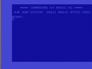
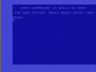
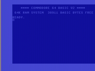
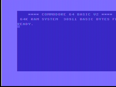
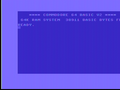
C64s have a one pixel wide solid white line at the extreme left edge of the display. But sometimes this pixel is actually two pixels wide. Or it is one pixel wide, but randomly the pixel will be doubled. This effect may not be visible directly but may require the chip to heat up first.
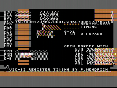
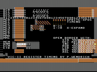
On the newer C64C models the VIC-II chip has the famous 'grey dot' bug, where a grey dot is displayed if a colour register is being changed by the CPU while the chip was reading it. This grey dot may or may not be visible, or flicker even, depending on the phase of the dot clock, and probably also the temperature.
The 'VSP bug', where the VIC-II corrupts memory if you update a certain register with the wrong value at the wrong time, may also be present only when the dot clock is in a certain phase.
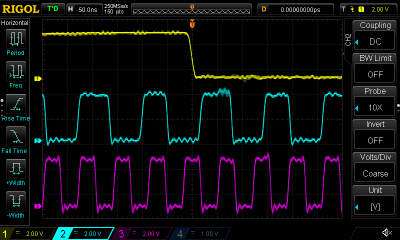
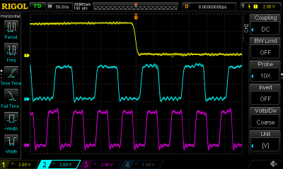
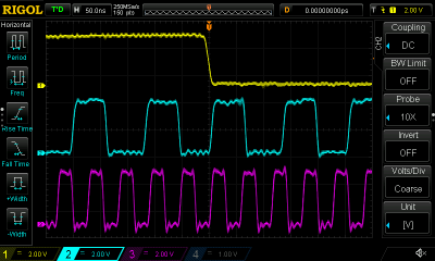
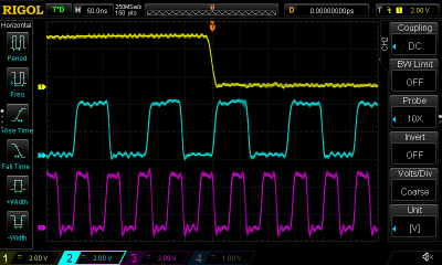
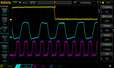
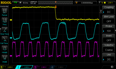
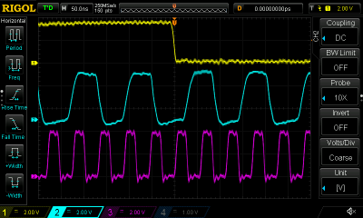
Below are come captures, made by probing the VIC-II chip clock pins using an oscilloscope, and also capturing the video output. On the oscilloscope traces below, the top (yellow) trace represents the main clock, the middle (blue) trace the dot clock and the lower (purple) trace the colour clock.
250425, PAL

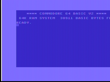
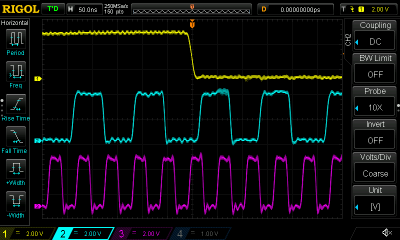
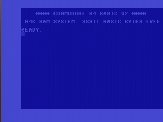
250469, PAL
For this board, I used a program called 'vicii_reg_timing.prg' to illustrate the grey dot problem this board has. This program can be found in the VICE test suite, for example.


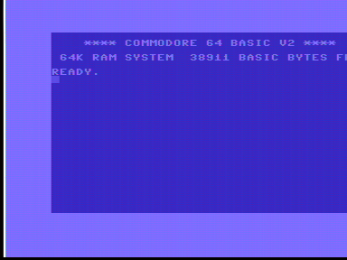
250425, NTSC