MOS 6569R5 ("VIC-II") video chip: Scope measurements
Equipment used: a Rigol DS1054Z oscilloscope.
I hooked up the IRQ pin to Channel 1. Then set up a trigger on the falling edge of the IRQ signal. The trigger is set at 3.5V. I have a small test program that can generate raster interrupts and sprite-collision interrupts so I can generate an IRQ at a certain X coordinate. (Assuming that the sprite IRQ fires as soon as the chip detects a collision. This is not quite the case, see below.)
Channel 2 is hooked up to the sync/luma output.
Channel 3 is connected to the PHI_0 clock output.
Channel 4 is sometimes also present based on the type of measurement.
Channels 1 and 3 are at 5V per division, others at 2V/division.
The Y coordinates mentioned in the captions correspond to the value of the raster counter.
The X coordinates are mostly guesswork based on the clock output, where I used the start of the falling edge as a baseline, and values defined in the chip's ROM.
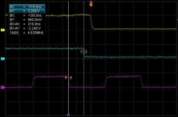
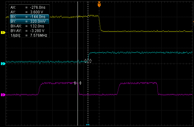
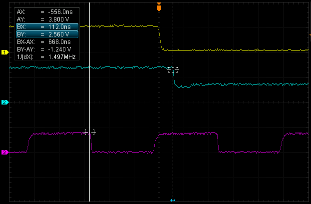
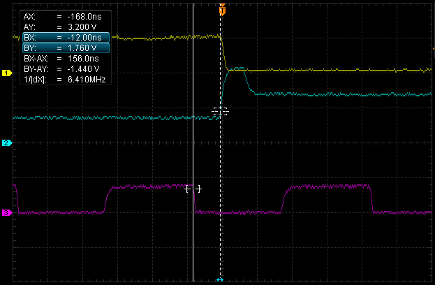
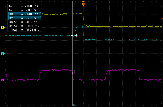
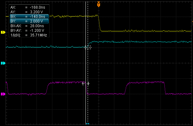
Vertical sync is implemented by inverting the sync/luma signal for three lines, in the sense that 'black' becomes 'blacker-than-black' and vice versa.
The vertical sync signal coincides with the raster interrupt, which in turns corresponds to an increment in the vertical counter. (In other words, Y increases when X=400.)
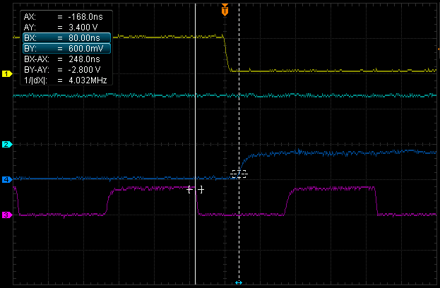
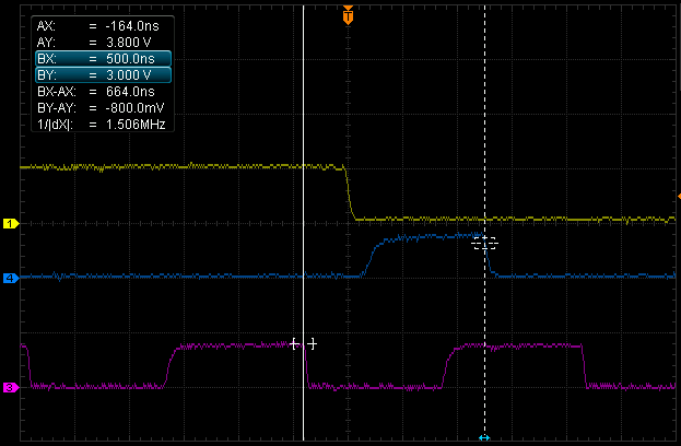
Raster interrupts appear to be generated roughly halfway during the low phase of the PHI_0 clock.
There is a subtle difference in the delay between the edge of the clock signal and the sync/interrupt signal in the two figures. It appears that something in the chip makes raster interrupts on even lines appear at a different time than on odd lines.
There is more silliness going on with the vertical synchronization but I'll leave that for another article.
* * *
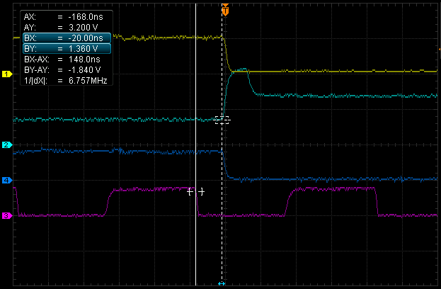
The following captures were made using sprite-collision, rather than raster interrupts.
Horizontal sync is similar to vertical sync, but it is generated by the horizontal rather than the vertical circuitry in the chip. Horizontal sync pulses occur every line except lines 301-309.
Except during lines 300-310, when it only generates sync signals, the chip also produces video output along with sync signals. Surrounding the horizontal sync there is a period of time during which the display must be blanked.
For a tiny moment at the start of the horizontal blanking interval the luma signal slightly undershoots the usual black level. This is more obvious on figure 16 below.
The voltage spike following the blank disable corresponds to a large white pixel. This is visible on a monitor as a white line on the entire left edge of the screen. This appears to be an artefact of the circuitry in the chip and cannot be turned off.
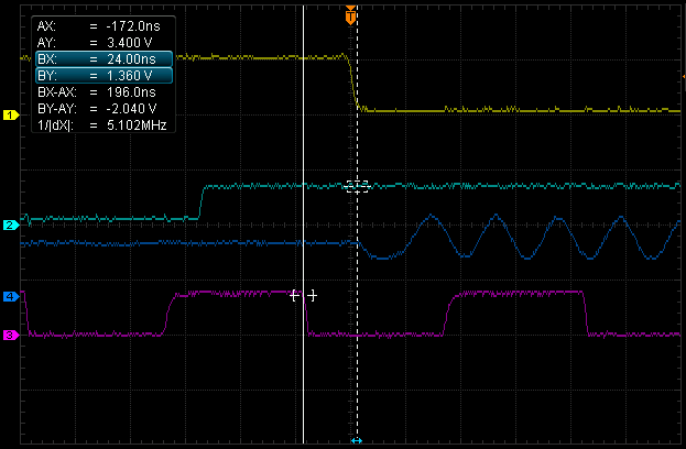
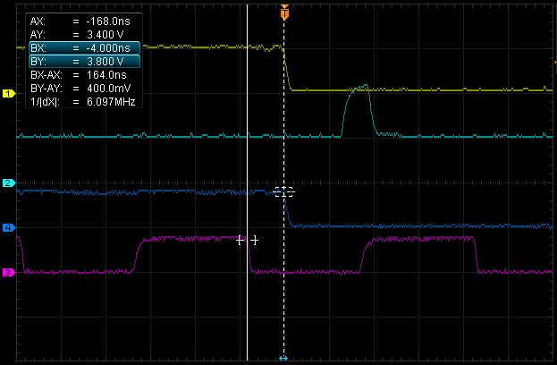
The color burst signal is generated during the horizontal blanking interval after the sync signal. Here I have hooked up the color (chroma) signal to channel 4.
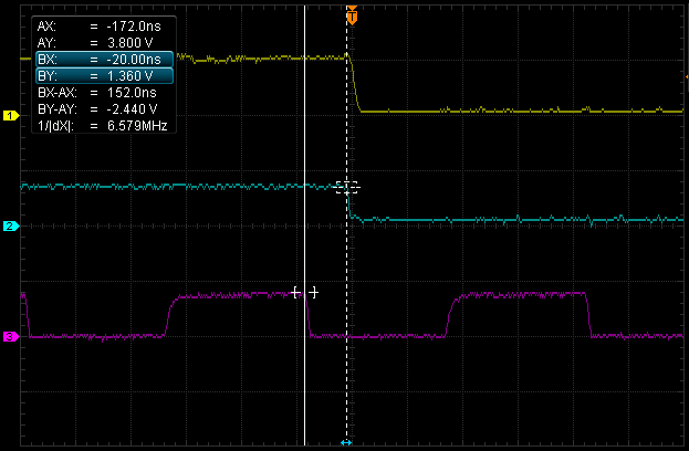
The main display (i.e. the bit in which you can put characters and sprites) starts and ends here. The X positions are encoded in ROM at 28-348 but it appears that all non-sync/blank video output is delayed by three pixels. In other words when you measure the luma signal the display actually appears at 31-351.
There is a slight peak in voltage at the start of the display. This corresponds to sprites that I placed there so I could get a collision IRQ.
The sprite collision IRQ appears to be 1 pixel behind the actual pixel display. Most of the times however the sprite collision IRQ precedes the display by three pixels, in accordance with the delay mentioned above. This is because the collision IRQs are only triggered during the low phase of PHI0. If a collision occurs during the other phase it will not register until PHI0 goes low. Presumably this is to make sure the collision register is stable in case the CPU wants to read it.

Here we meet the BA line, at channel #4. This line is made low by the chip whenever it needs the bus for extra memory accesses. In this case it is to read 40 bytes of character and color data. This is what is known as a 'bad line'. Bad for the CPU because it is (for the most part) halted while BA is low.
The 'enable BA' and 'disable horizontal blanking' events occur at the same time.
When 'disable BA' occurs the 40-column window is still active.
The chip needs the bus also to fetch two bytes of sprite data on each line on which the sprite is active. Since BA needs to go low three cycles in advance, the ROM is set up so that BA for sprite 0 starts at X=328 and ends at X=368.
BA for sprite 0 starts exactly when BA for character fetch would have ended.
The peak in the luma signal is from sprites 0 and 7 placed there for IRQ generation. In fact there is a similar, less obvious peak in figure 12.
Note that the IRQ is now ahead of the pixel!
I mentioned just now that BA for sprite 0 starts when BA for character fetch ends. There is however one exception to this: when the first line for sprite 0 is fetched, the lowering of BA is delayed by about half a cyle. So if you have a bad line with sprite 0 becoming active on the next line you see a tiny peak where BA briefly becomes high again! Apparently this peak is short enough or timed in such a way that it does not affect the CPU.
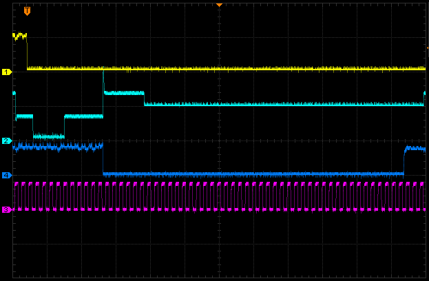
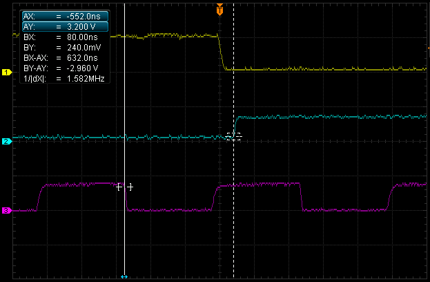
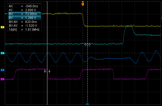
Finally here is a capture of an entire (bad) line. Actually there are some cycles missing on the right but these do not matter. Also I left out the color burst due to running out of channels.
I used the scope's memory readout of this capture to verify most of the X coordinates.
The events you see here are, from left to right:
| X-coord. | Event |
|---|---|
| 388 | Enable horizontal blanking |
| 400 | Increase vertical counter (raster interrupt) |
| 408 | Enable horizontal sync |
| 444 | Disable horizontal sync |
| 488 | Disable horizontal blanking / Enable BA for char fetch |
| 28 (31) | Enable 40-column display |
| 328 | Disable BA for char fetch |
| 348 (351) | Disable 40-column display |
Michiel Boland
April 2019
Updated May 2019 (explained collision IRQ delay)