VIC-II synchronization (PAL)

| signal | description | set | reset | set | reset |
| veq | vertical equalization | y=301 | y=310 | ||
| hsync | horizontal sync | x=408 | x=444 | ||
| heq | horizontal equalization | x=174 | x=192 | x=426 | x=444 |
| vsync | vertical sync | y=304 | y=307 |
The VIC-II chips generates a sync signal based on the above schematic.
The net result is:
During normal operation veq and vsync are both zero. The sync pulse is then determined by hsync. This results in a sync pulse every line for 36 pixels (approx 4.6 us).
Vertical sync is preceded by three lines with veq=1, vsync=0. During these lines the hsync pulse is ignored and replaced with the horizontal equalization pulse. This results in two short (18 pixel) pulses per line.
When vsync turns on, the sync signal essentially becomes an inverted heq which results in two long pulses per line.
We then have three sync lines with veq=1, vsync=1.
Finally we get another set of three equalization lines.
Plotted in X/Y-coordinates, the resulting signal then looks a bit like this: (green=sync active)
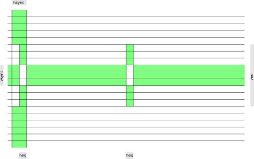
Note that Y gets incremented when X is about 400.
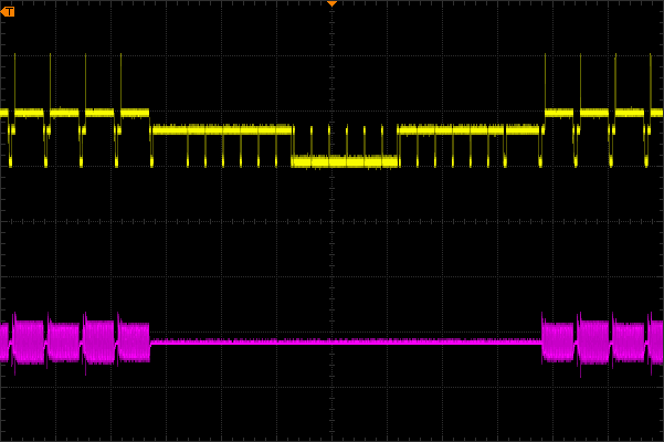
Oscilloscope capture, yellow=luma/sync, purple=chroma:
Michiel Boland
July 2019